
Scenario 23
License

If you want to use the dataset or scripts on this page, please use the link below to generate the final list of papers that need to be cited.
Overview
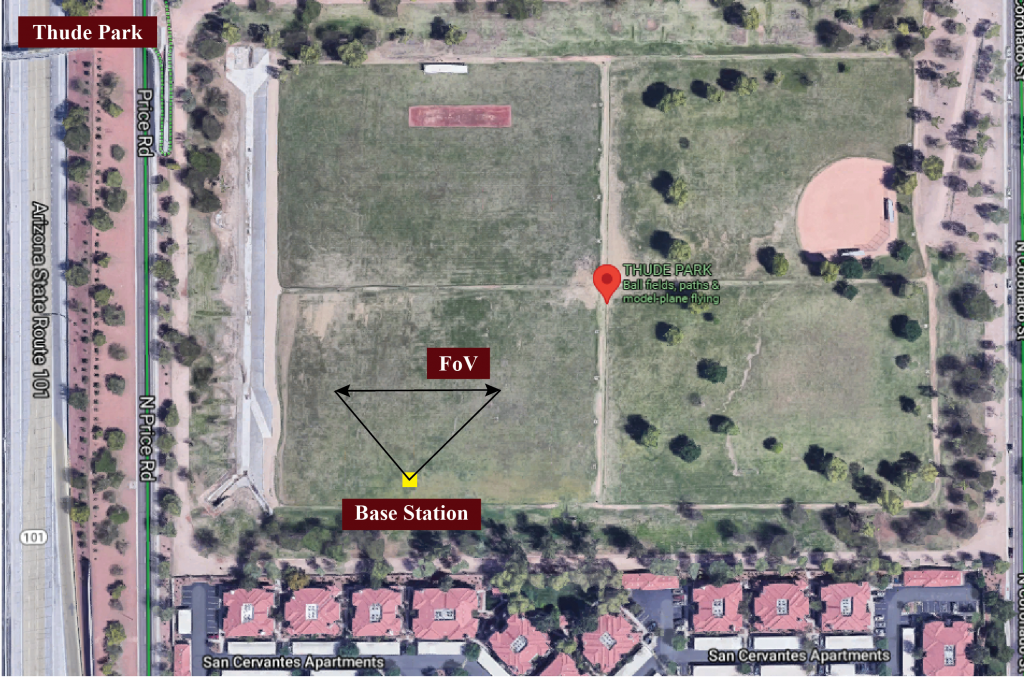
Scenario 23 is designed to study high-frequency wireless communication applications with drones. The adopted testbed comprises of two units. Unit 1 primarily consists of a stationary base station equipped with an RGB camera and a mmWave phased array. The stationary unit adopts a 16-element 60GHz-band phased array and it receives the transmitted signal using an over-sampled codebook of 64 pre-defined beams. The mmWave phased array and the RGB camera are placed on a table at a height of ~ 1.5 meters from the ground level. Both the camera and the phased array are facing towards the sky, which helps increase the basestation’s field-of-view (FoV). The second unit (Unit 2) is an RC drone equipped with a mmWave transmitter, GPS receiver, and inertial measurement units (IMU). The transmitter consists of a quasi-omni antenna constantly transmitting (omnidirectional) at the 60 GHz band. Please refer to the detailed description of the testbed presented here.
Thude Park: It is a public use rectangular park located in Chandler, Arizona. The circumference of the overall park is ~1.24 Kilometers. The park consists of a dedicated open field for flying model aircraft, including RC drones. The length and breadth of the RC flying area are 205 meters and 152 meters, respectively. The dedicated flying zone makes it safe and ideal for this drone-based scenario. The length and breadth of the RC flying zone make it possible to collect data at different distances and heights from the base station and at varying speeds, resulting in a diverse and realistic dataset.
Collected Data
Overview
Number of Data Collection Units: 2 (using DeepSense Testbed #4)
Number of Data Samples: 11387
Data Modalities: RGB images, 64-dimensional received power vector, GPS locations, height, compass heading, pitch and yaw
Average Data Capture Rate: 10 FPS
Sensors at Unit 1: (Stationary Receiver)
- Wireless Sensor [Phased Array]: A 16-element antenna array operating in the 60 GHz frequency band and receives the transmitted signal using an over-sampled codebook of 64 pre-defined beams
- Visual Sensor [Camera]: The main visual perception element in the testbed is an RGB-D camera. The camera is used to capture RGB images of 960×540 resolution at a base frame rate of 30 frames per second (fps)
- Position Sensor [GPS Receiver]: A GPS-RTK receiver for capturing accurate real-time locations for the stationary unit
Sensors at Unit 2: (Mobile Transmitter)
- Position Sensor [GPS Receiver]: A GPS-RTK receiver is installed on the top of the mobile unit and is used to capture accurate real-time locations at 10 frames per second (fps). The collected data comprises the Latitude and Longitude information in addition to other important data
| Testbed | 1 |
|---|---|
| Instances | 11387 |
| Number of Units | 2 |
| Total Data Modalities | RGB images, 64-dimensional received power vector, GPS locations, height, speed, compass heading, pitch, roll |
| Unit1 | |
| Type | Stationary |
| Hardware Elements | RGB camera, mmWave phased array receiver, GPS receiver |
| Data Modalities | RGB images, 64-dimensional received power vector, GPS locations |
| Unit2 | |
| Type | Mobile |
| Hardware Elements | mmWave omni-directional transmitter, GPS receiver, IMU |
| Data Modalities | GPS locations, height, speed, compass heading, pitch, roll |
Data Visualization
Download
To download the scenario dataset, click on the link below.
How to Access Scenario 23 Data?
Step 1. Download Scenario 23 Data
Step 2. Extract the scenario23.zip file
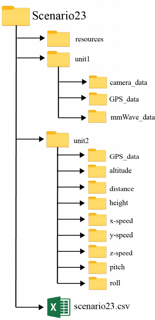
Scenario 23 folder consists of three sub-folders:
- unit1: Includes the data captured by unit 1
- unit2: Includes the data captured by unit 2
- resources: Includes the scenario-specific annotated dataset, data labels and other additional information. For more details, refer the resources section below.
Scenario 23 folder also includes the “scenario23.csv” file with the paths to all the collected data. For each coherent time, we provide the corresponding visual, wireless and GPS data.
Resources
What are the Additional Resources?
Resources consist of the following information:
- visual data annotations: For the visual data, we provide the coordinates of the 2D bounding box and attributes for each frame
- data labels: The labels comprise the ground-truth beam indices computed from the mmWave received power vectors and the sequence index
- additional information: Includes the scenario-specific additional data. Details of the information is provided below
Visual Data Annotations
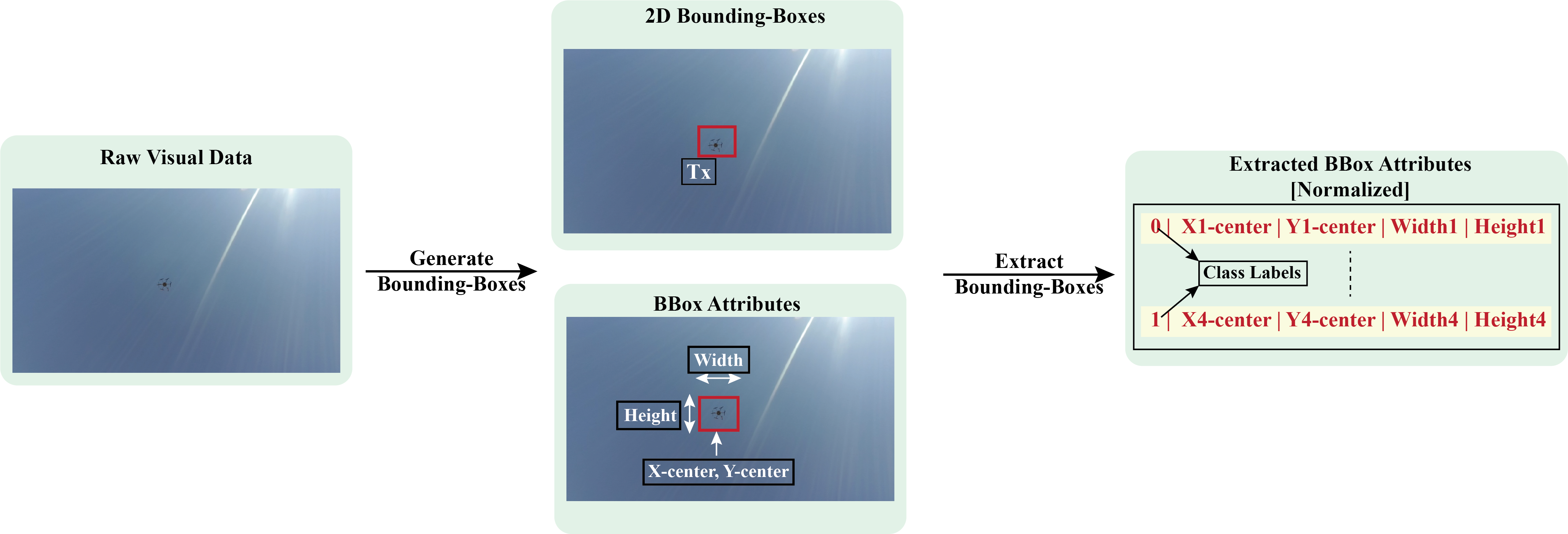
After performing the post-processing steps presented here, we generate the annotations for the visual data. Using state-of-the-art machine learning algorithms and multiple validation steps, we achieve highly accurate annotations. In this particular scenario, we provide the coordinates of the 2D bounding box and attributes for each frame. We, also, provide the ground-truth labels for 2 object classes, “Tx”, and “Distractor”. The “Tx” refers to the transmitting drone in the scene and the “Distractor” for any other objects, such as birds, other drones, etc. We follow the YOLO format for the bounding-box information. In the YOLO format, each bounding box is described by the center coordinates of the box and its width and height. Each number is scaled by the dimensions of the image; therefore, they all range between 0 and 1. Instead of category names, we provide the corresponding integer categories. We follow the following assignment: (i) “Tx” as “0” , and (ii) “Distractor” as “1”.
Data Labels
The labels comprises of the ground-truth beam indices computed from the mmWave received power vectors, the direction of travel (unit2), and the sequence index.
- Ground-Truth Beam: The phased array of unit 1 utilizes an over-sampled beamforming codebook of N = 64 vectors, which are designed to cover the field of view. It captures the received power by applying the beamforming codebook elements as a combiner. For each received power vector of dimension [64 x 1], the index with the maximum received power value is selected as the optimal beam index. This data is provided in column 17 [‘unit1_beam_index’] of the scenario23.csv
- Sequence Index: During the data collection process, the mobile transmitter (unit2) travelled multiple times in front of the base station (unit1). For each run, the testbed collects multiple data samples. All the data samples with the same sequence index belongs to the same run
Additional Information
We, further, provide additional information for each sample present in the scenario dataset. The details are provided in columns 8 – 16 of the scenario23.csv. The contents of the additional data are listed below:
- index: It represents the sample number
- time_stamp[UTC]: This represents the time of data capture in “hr-mins-secs-ms” format
- drone parameters:
- unit2_speed
- unit2_altitude
- unit2_distance
- unit2_height
- unit2_x-speed
- unit2_y-speed
- unit2_z-speed
- unit2_pitch
- unit2_roll
An example table comprising of the data labels and the additional information is shown below.
| index | unit1_rgb | unit1_pwr_60ghz | unit1_loc | unit2_loc | unit2_speed | unit2_altitude | unit2_distance | unit2_height | unit2_x-speed | unit2_y-speed | unit2_z-speed | unit2_pitch | unit2_roll | seq_index | time_stamp[UTC] |
|---|---|---|---|---|---|---|---|---|---|---|---|---|---|---|---|
| 1 | ./unit1/camera_data/image_BS1_1_16_58_42.jpg | ./unit1/mmWave_data/mmWave_power_1.txt | ./unit1/GPS_data/gps_location.txt | ./unit2/GPS_data/gps_location_1.txt | ./unit2/speed/speed_1.txt | ./unit2/altitude/altitude_1.txt | ./unit2/distance/distance_1.txt | ./unit2/height/height_1.txt | ./unit2/x_speed/x_speed_1.txt | ./unit2/y_speed/y_speed_1.txt | ./unit2/z_speed/z_speed_1.txt | ./unit2/pitch/pitch_1.txt | ./unit2/roll/roll_1.txt | 1 | ['16-58-42-0'] |
| 2 | ./unit1/camera_data/image_BS1_2_16_58_42.jpg | ./unit1/mmWave_data/mmWave_power_2.txt | ./unit1/GPS_data/gps_location.txt | ./unit2/GPS_data/gps_location_2.txt | ./unit2/speed/speed_2.txt | ./unit2/altitude/altitude_2.txt | ./unit2/distance/distance_2.txt | ./unit2/height/height_2.txt | ./unit2/x_speed/x_speed_2.txt | ./unit2/y_speed/y_speed_2.txt | ./unit2/z_speed/z_speed_2.txt | ./unit2/pitch/pitch_2.txt | ./unit2/roll/roll_2.txt | 1 | ['16-58-42-142'] |
| 3 | ./unit1/camera_data/image_BS1_3_16_58_42.jpg | ./unit1/mmWave_data/mmWave_power_3.txt | ./unit1/GPS_data/gps_location.txt | ./unit2/GPS_data/gps_location_3.txt | ./unit2/speed/speed_3.txt | ./unit2/altitude/altitude_3.txt | ./unit2/distance/distance_3.txt | ./unit2/height/height_3.txt | ./unit2/x_speed/x_speed_3.txt | ./unit2/y_speed/y_speed_3.txt | ./unit2/z_speed/z_speed_3.txt | ./unit2/pitch/pitch_3.txt | ./unit2/roll/roll_3.txt | 1 | ['16-58-42-284'] |
| 4 | ./unit1/camera_data/image_BS1_4_16_58_42.jpg | ./unit1/mmWave_data/mmWave_power_4.txt | ./unit1/GPS_data/gps_location.txt | ./unit2/GPS_data/gps_location_4.txt | ./unit2/speed/speed_4.txt | ./unit2/altitude/altitude_4.txt | ./unit2/distance/distance_4.txt | ./unit2/height/height_4.txt | ./unit2/x_speed/x_speed_4.txt | ./unit2/y_speed/y_speed_4.txt | ./unit2/z_speed/z_speed_4.txt | ./unit2/pitch/pitch_4.txt | ./unit2/roll/roll_4.txt | 1 | ['16-58-42-426'] |
| 5 | ./unit1/camera_data/image_BS1_5_16_58_42.jpg | ./unit1/mmWave_data/mmWave_power_5.txt | ./unit1/GPS_data/gps_location.txt | ./unit2/GPS_data/gps_location_5.txt | ./unit2/speed/speed_5.txt | ./unit2/altitude/altitude_5.txt | ./unit2/distance/distance_5.txt | ./unit2/height/height_5.txt | ./unit2/x_speed/x_speed_5.txt | ./unit2/y_speed/y_speed_5.txt | ./unit2/z_speed/z_speed_5.txt | ./unit2/pitch/pitch_5.txt | ./unit2/roll/roll_5.txt | 1 | ['16-58-42-568'] |
| 6 | ./unit1/camera_data/image_BS1_6_16_58_42.jpg | ./unit1/mmWave_data/mmWave_power_6.txt | ./unit1/GPS_data/gps_location.txt | ./unit2/GPS_data/gps_location_6.txt | ./unit2/speed/speed_6.txt | ./unit2/altitude/altitude_6.txt | ./unit2/distance/distance_6.txt | ./unit2/height/height_6.txt | ./unit2/x_speed/x_speed_6.txt | ./unit2/y_speed/y_speed_6.txt | ./unit2/z_speed/z_speed_6.txt | ./unit2/pitch/pitch_6.txt | ./unit2/roll/roll_6.txt | 1 | ['16-58-42-710'] |
| 7 | ./unit1/camera_data/image_BS1_7_16_58_42.jpg | ./unit1/mmWave_data/mmWave_power_7.txt | ./unit1/GPS_data/gps_location.txt | ./unit2/GPS_data/gps_location_7.txt | ./unit2/speed/speed_7.txt | ./unit2/altitude/altitude_7.txt | ./unit2/distance/distance_7.txt | ./unit2/height/height_7.txt | ./unit2/x_speed/x_speed_7.txt | ./unit2/y_speed/y_speed_7.txt | ./unit2/z_speed/z_speed_7.txt | ./unit2/pitch/pitch_7.txt | ./unit2/roll/roll_7.txt | 1 | ['16-58-42-852'] |
| 8 | ./unit1/camera_data/image_BS1_8_16_58_43.jpg | ./unit1/mmWave_data/mmWave_power_8.txt | ./unit1/GPS_data/gps_location.txt | ./unit2/GPS_data/gps_location_8.txt | ./unit2/speed/speed_8.txt | ./unit2/altitude/altitude_8.txt | ./unit2/distance/distance_8.txt | ./unit2/height/height_8.txt | ./unit2/x_speed/x_speed_8.txt | ./unit2/y_speed/y_speed_8.txt | ./unit2/z_speed/z_speed_8.txt | ./unit2/pitch/pitch_8.txt | ./unit2/roll/roll_8.txt | 1 | ['16-58-43-0'] |
| 9 | ./unit1/camera_data/image_BS1_9_16_58_43.jpg | ./unit1/mmWave_data/mmWave_power_9.txt | ./unit1/GPS_data/gps_location.txt | ./unit2/GPS_data/gps_location_9.txt | ./unit2/speed/speed_9.txt | ./unit2/altitude/altitude_9.txt | ./unit2/distance/distance_9.txt | ./unit2/height/height_9.txt | ./unit2/x_speed/x_speed_9.txt | ./unit2/y_speed/y_speed_9.txt | ./unit2/z_speed/z_speed_9.txt | ./unit2/pitch/pitch_9.txt | ./unit2/roll/roll_9.txt | 1 | ['16-58-43-125'] |
| 10 | ./unit1/camera_data/image_BS1_10_16_58_43.jpg | ./unit1/mmWave_data/mmWave_power_10.txt | ./unit1/GPS_data/gps_location.txt | ./unit2/GPS_data/gps_location_10.txt | ./unit2/speed/speed_10.txt | ./unit2/altitude/altitude_10.txt | ./unit2/distance/distance_10.txt | ./unit2/height/height_10.txt | ./unit2/x_speed/x_speed_10.txt | ./unit2/y_speed/y_speed_10.txt | ./unit2/z_speed/z_speed_10.txt | ./unit2/pitch/pitch_10.txt | ./unit2/roll/roll_10.txt | 1 | ['16-58-43-250'] |