
Scenario 35
License

If you want to use the dataset or scripts on this page, please use the link below to generate the final list of papers that need to be cited.
Overview
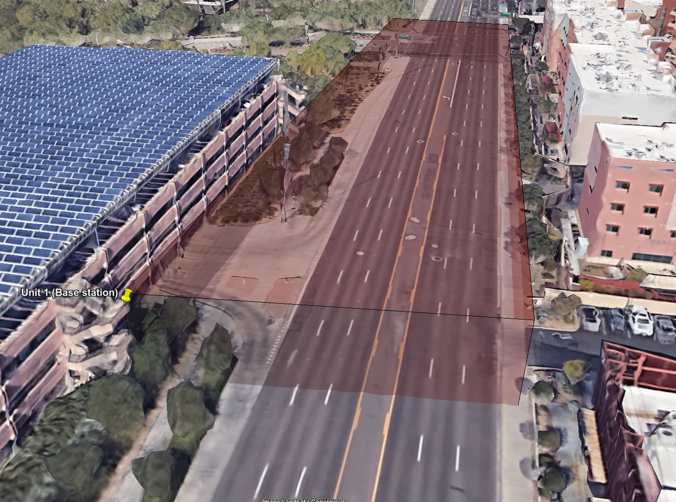
The data collection setup of Scenarios 35 (outdoor). The figure shows the location of Unit 1 (base station) with (latitude, longitude) = (33.41766367, -111.9265825). In this scenario, Unit 2 (a car) will drive on the road in the field of view (red-shaded volume) of the base station antenna, camera, and radar.
Scenario 35 is collected in an outdoor wireless environment representing a six-lane city street with two-way traffic. The testbed adopted in this scenario comprises of three units. Unit 1 primarily consists of a stationary base station equipped with an RGB camera, a LiDAR sensor, an FMCW radar, and a mmWave phased array. The stationary unit adopts a 16-element 60GHz-band phased array and it receives the transmitted signal using an over-sampled codebook of 64 pre-defined beams. The second unit (Unit 2) is a mobile vehicle unit equipped with a mmWave transmitter and GPS receiver. The transmitter consists of a quasi-omnidirectional antenna continually transmitting in the 60 GHz band. The radar consists uses 1 Tx and 4 Rx antennas with operational frequency range is 76 to 81 GHz and 4 GHz bandwidth. It has a maximum range of ~100 meters with a range resolution of 60 cm making it highly suitable for this vehicular-communication application. Each data sample has multiple modalities including an RGB image, and FMCW radar data both collected by Unit 1. Refer to the detailed description of the testbed presented in Testbed 1.
Scope: This scenario targets a low SINR regime. Throughout the scenario, the optimum beam from the base station (unit 1) to the user (unit 2) is only a few dB better than the noise floor, resulting in a challenging environment, e.g., for beam prediction. The low received power at unit 2 can be visualized in video of the scenario further below.
Rural Road: It is a two-way street with 6 lanes (3 lanes on each side with a passing lane in-between), a width of ~24 meters, and a vehicle speed limit of 45mph (72.42 kph). The wider street and the higher speed limit present an opportunity to incorporate diversity in the dataset. Furthermore, it is one of the busiest streets in Downtown Tempe, making it host of a large variety of vehicles such as buses, trucks, SUVs, and bikes, to name a few. In terms of wireless communication, the presence of big vehicles present the possibility of partial or complete UE blockage. All these make the location diverse from visual and wireless perspectives alike.
Collected Data
Overview
Data Modalities: RGB images, mmWave beam powers, mmWave radar, GPS locations
Data Capture Rate: 10 Hz
Sensors at Unit 1: (Stationary Receiver)
- Wireless Sensor [Phased Array]: A 16-element antenna array operating in the 60 GHz frequency band and receives the transmitted signal using an over-sampled codebook of 64 pre-defined beams
- Visual Sensor [Camera]: The main visual perception element in the testbed is an RGB-D camera. The camera is used to capture RGB images of 960×540 resolution.
- Position Sensor [GPS Receiver]: A GPS-RTK receiver for capturing accurate real-time locations for the stationary unit.
- MmWave radar sensor [Ranging sensor]: Thehe Frequency Modulated Continuous Wave (FMCW) radar collects 3D complex radar frame/samples of dimension (# of RX antennas) x (# of samples per chirp) x (# of chirps per frame).
- Active TX antennas: 1
- Active RX antennas: 4
- # of samples per chirp: 256
- # of chirps per frame: 128
- ADC sampling rate: 5000 Ksps
- Chirp slope: 15.015 MHz/us
- Chirp Start Frequency: 77 GHz
- Ramp end time: 60 us
- ADC start time: 6 us
- Idle time: 5 us
- Receiver gain: 30dB
- Radar frames per second: 10
Sensors at Unit 2: (Mobile Transmitter)
- Position Sensor [GPS Receiver]: A GPS-RTK receiver installed on the top of the mobile unit and is used to capture accurate real-time locations. The collected data comprises Latitude and Longitude position values.
| Testbed | 1 |
|---|---|
| Number of Samples | 3045 |
| Number of Units | 2 |
| Data Modalities | RGB images, 64-dimensional received power vector, GPS locations, Radar data |
| Unit1 | |
| Type | Stationary |
| Hardware Elements | RGB camera, mmWave phased array receiver, GPS receiver, mmWave Radar System |
| Data Modalities | RGB images, 64-dimensional received power vector, GPS locations, Radar data |
| Unit2 | |
| Type | Mobile |
| Hardware Elements | mmWave omni-directional transmitter, GPS receiver |
| Data Modalities | GPS locations |
Data Visualization
Download
Please login to download the DeepSense datasets
How to Access Scenario 35 Data?
Step 1. Download Scenario 35 Data
Step 2. Extract the scenario35.zip file
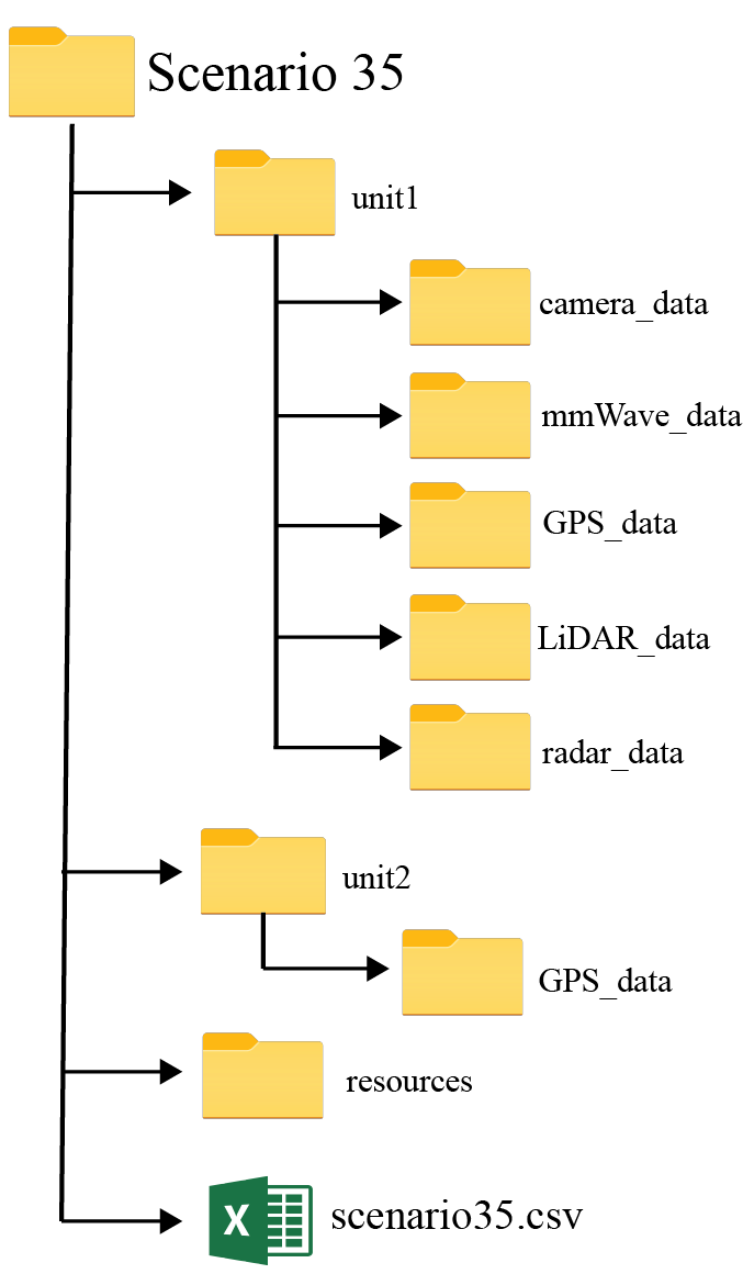
Scenario 35 folder consists of three sub-folders:
- unit1: Includes the data captured by unit 1
- unit2: Includes the data captured by unit 2
- resources: Includes the scenario-specific annotated dataset, data labels and other additional information. For more details, refer the resources section below.
Scenario 35 folder also includes the “scenario 35.csv” file with the paths to all the collected data. For each coherent time, we provide the corresponding visual, wireless and GPS data.
Resources
What are the Additional Resources?
Resources consist of the following information:
- data labels: The labels comprises of the ground-truth beam indices computed from the mmWave received power vectors, the direction of travel (unit2), and the sequence index
- additional information: Includes the scenario-specific additional data. Details of the information is provided below
Data Labels
The labels comprises of the ground-truth beam indices computed from the mmWave received power vectors, the direction of travel (unit2), and the sequence index.
- Ground-Truth Beam: The phased array of unit 1 utilizes an over-sampled beamforming codebook of N = 64 vectors, which are designed to cover the field of view. It captures the received power by applying the beamforming codebook elements as a combiner. For each received power vector of dimension [64 x 1], the index with the maximum received power value is selected as the optimal beam index. This data is provided in the ‘best_beam’ column of the scenario35.csv.
- Maximum Received Power: The received power in Unit 2 from the optimum beam beamformed at Unit 1. This data is provided in the ‘max_power’ column of the scenario35.csv.
- Sequence Index: During the data collection process, the mobile transmitter (unit2) travelled multiple times in front of the base station (unit1). For each run, the testbed collects multiple data samples. All the data samples with the same sequence index belongs to the same run. This data is provided in the column ‘seq_index’ of the scenario35.csv.
- Radar_label_bool: When TRUE, indicates the vehicle is detected in the radar. When FALSE, the vehicle is not detected in the radar.
- Radar_label: Additional information about the targets detected in the radar image:
- “id”: ID of the detected target in the sample
- “n_peaks”: number of peaks within the target
- “points”: The indices of the peaks in the radar cube
- “avg”: average value of the peaks,
- “bounds”: radar cube bounds of the peak,
- “selected”: if the target is the transmitter,
- “box_min”: minimum x and y pixel values of the bounding box of the target,
- “box_max”: minimum x and y pixel values of the bounding box of the target
- Example value of the label:
{“id”: 0,
“n_peaks”: 3,
“points”: [[128, 414, 76], [130, 415, 76], [131, 415, 73]],
“avg”: [129.67, 414.67, 75.0],
“bounds”: [[128, 414, 73], [131, 415, 76]],
“selected”: false,
“box_min”: [1.0, 95],
“box_max”: [8.0, 100]},
“id”: 1, (…)}
Additional Information
We further provide additional information for each sample present in the scenario dataset. The contents of the additional data are listed below:
- index: It represents the sample number
- time_stamp[UTC]: This represents the time of data capture in “hr-mins-secs-ms” format
Warning on NaN values: Some samples (<1%) in the column ‘unit1_pwr_60ghz’ contain NaNs (not-a-value). These NaNs result from random, real-world sensor errors. In the context of received power, NaNs can be considered as zeros. Assuming that pwr_vect is our received power vector, one can explicitly convert the NaNs into zeros by doing pwr_vect(isnan(pwr_vect)) = 0 in Matlab or pwr_vect[np.isnan(pwr_vect)] = 0 in Python.
An example table comprising of the first 10 rows of data modalities, labels and additional information
| abs_idx | seq_index | timestamp | unit1_gps | unit1_pwr | unit1_rgb | unit1_radar | unit2_gps | best_beam | max_power | radar_label_bool | radar_label |
|---|---|---|---|---|---|---|---|---|---|---|---|
| 1 | 1 | 17:04:11-700000 | ./unit1/gps/unit1_static_loc.txt | ./unit1/pwr/data_873.txt | ./unit1/rgb/image_BS2_873_17-04-11.jpg | ./unit1/radar/data_872_00-04-11_810.npy | ./unit2/gps/data_4054.txt | 13 | 0.145170003 | FALSE | ./resources/radar_label/label_0.txt |
| 2 | 1 | 17:04:11-800000 | ./unit1/gps/unit1_static_loc.txt | ./unit1/pwr/data_874.txt | ./unit1/rgb/image_BS2_874_17-04-11.jpg | ./unit1/radar/data_873_00-04-11_921.npy | ./unit2/gps/data_4055.txt | 15 | 0.134134009 | TRUE | ./resources/radar_label/label_1.txt |
| 3 | 1 | 17:04:11-900000 | ./unit1/gps/unit1_static_loc.txt | ./unit1/pwr/data_875.txt | ./unit1/rgb/image_BS2_875_17-04-11.jpg | ./unit1/radar/data_874_00-04-12_031.npy | ./unit2/gps/data_4056.txt | 16 | 0.133056447 | FALSE | ./resources/radar_label/label_2.txt |
| 4 | 1 | 17:04:12-000000 | ./unit1/gps/unit1_static_loc.txt | ./unit1/pwr/data_876.txt | ./unit1/rgb/image_BS2_876_17-04-12.jpg | ./unit1/radar/data_875_00-04-12_143.npy | ./unit2/gps/data_4057.txt | 16 | 0.135151446 | FALSE | ./resources/radar_label/label_3.txt |
| 5 | 1 | 17:04:12-100000 | ./unit1/gps/unit1_static_loc.txt | ./unit1/pwr/data_877.txt | ./unit1/rgb/image_BS2_877_17-04-12.jpg | ./unit1/radar/data_875_00-04-12_143.npy | ./unit2/gps/data_4058.txt | 15 | 0.135949448 | FALSE | ./resources/radar_label/label_4.txt |
| 6 | 1 | 17:04:12-200000 | ./unit1/gps/unit1_static_loc.txt | ./unit1/pwr/data_878.txt | ./unit1/rgb/image_BS2_878_17-04-12.jpg | ./unit1/radar/data_876_00-04-12_254.npy | ./unit2/gps/data_4059.txt | 16 | 0.140475959 | TRUE | ./resources/radar_label/label_5.txt |
| 7 | 1 | 17:04:12-300000 | ./unit1/gps/unit1_static_loc.txt | ./unit1/pwr/data_879.txt | ./unit1/rgb/image_BS2_879_17-04-12.jpg | ./unit1/radar/data_877_00-04-12_365.npy | ./unit2/gps/data_4060.txt | 16 | 0.130482331 | TRUE | ./resources/radar_label/label_6.txt |
| 8 | 1 | 17:04:12-400000 | ./unit1/gps/unit1_static_loc.txt | ./unit1/pwr/data_880.txt | ./unit1/rgb/image_BS2_880_17-04-12.jpg | ./unit1/radar/data_878_00-04-12_476.npy | ./unit2/gps/data_4061.txt | 16 | 0.137830794 | TRUE | ./resources/radar_label/label_7.txt |
| 9 | 1 | 17:04:12-500000 | ./unit1/gps/unit1_static_loc.txt | ./unit1/pwr/data_881.txt | ./unit1/rgb/image_BS2_881_17-04-12.jpg | ./unit1/radar/data_879_00-04-12_587.npy | ./unit2/gps/data_4062.txt | 16 | 0.139642745 | TRUE | ./resources/radar_label/label_8.txt |
| 10 | 1 | 17:04:12-600000 | ./unit1/gps/unit1_static_loc.txt | ./unit1/pwr/data_882.txt | ./unit1/rgb/image_BS2_882_17-04-12.jpg | ./unit1/radar/data_880_00-04-12_698.npy | ./unit2/gps/data_4063.txt | 17 | 0.132877886 | FALSE | ./resources/radar_label/label_9.txt |