
Scenario 32
License

If you want to use the dataset or scripts on this page, please use the link below to generate the final list of papers that need to be cited.
Overview
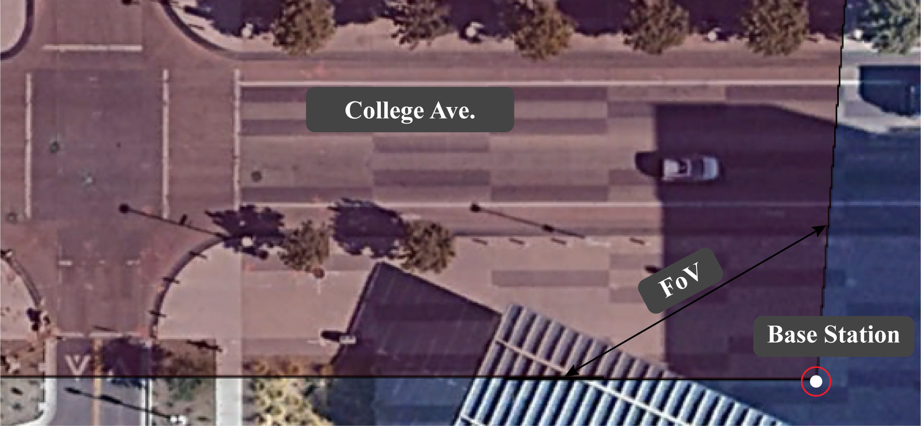

The figure on the left shows the elevation view of the street and the surroundings in scenario 32. The field of view (FoV) of the base station (Unit 1) is highlighted. The figure on the right shows the traffic and street view from Unit 1 perspective.
Scenario 32 is collected in an outdoor wireless environment representing a two-way city street. The DeepSense Testbed is deployed in this environment where the two units are placed on the opposite sides of the street. The transmitter (Unit 2) constantly transmits using one antenna element of the phased array to realize omnidirectional transmission. The receiver continuously scans the surrounding environment using a receive mmWave beam steering codebook of 64 beams and by measuring the receive power with each beam. The average sampling rate is 10 samples/s. Each data sample includes an RGB image, a 64-element receive power vector, a 3D LiDAR image, and an FMCW radar signal, all collected by Unit 1. Please refer to the detailed description of the testbed presented here.
College Ave: It is a two-way street with 2 lanes, a width of 13 meters, and a vehicle speed limit of 25mph (40.6 km per hour). It is worth mentioning here that since this is a city street, vehicles of various sizes and travel speeds pass in both directions, along with pedestrians walking on both sides of the street. This creates a diverse pool of blockages for the LOS link between the transmitter and receiver, which results in diverse received power maps (i.e., diverse power fluctuations across all 64 beam over time instances) and a diverse dataset.
Collected Data
Overview
Number of Data Collection Units: 2 (using DeepSense Testbed #5)
Total Number of Data Samples: 3235
Data Modalities: RGB images, 64-dimensional received power vector, GPS locations, a 3D LiDAR image, and an FMCW radar signal
Sensors at Unit 1: (Stationary Receiver)
- Wireless Sensor [Phased Array]: A 16-element antenna array operating in the 60 GHz frequency band and receives the transmitted signal using an over-sampled codebook of 64 pre-defined beams
- Visual Sensor [Camera]: The main visual perception element in the testbed is an RGB-D camera. The camera is used to capture RGB images of 960×540 resolution at a base frame rate of 30 frames per second (fps)
- Position Sensor [GPS Receiver]: A GPS-RTK receiver for capturing accurate real-time locations for the stationary unit 1
- LiDAR Sensor [3D laser scanner]: This system provides the range and angle data of objects within its range of view. The scanning range of the 3D LiDAR is 100 meters and the maximum motor spin frequency is 20Hz.
- MmWave radar sensor [Ranging sensor]: For the Frequency Modulated Continuous Wave (FMCW) radar, we adopted a set of radar parameters based on the Texas Instrument (TI’s) short range radar (SRR) example, given by B = 750 MHz, µ = 15 MHz/us, A = 128 chirps/frame, S = 256 samples/chirp. These settings provide the maximum range of 45m and the maximum velocity of 56 km/h.
- MmWave radar sensor [Ranging sensor]: For the Frequency Modulated Continuous Wave (FMCW) radar each sample contains a 3D complex radar frame samples of (# of RX antennas) x (# of samples per chirp) x (# of chirps per frame).
- Active TX antennas: 1
- Active RX antennas: 4
- #of samples per chirp: 256
- # of chirps per frame: 250
- ADC sampling rate: 6200 Ksps
- Chirp slope: 8.014 MHz/us
- Chirp Start Frequency: 77 GHz
- Ramp end time: 47.5 us
- ADC start time: 4.2 us
- Idle time: 2 us
- Receiver gain: 30dB
- Radar frames per second: 10
Sensors at Unit 2: (Mobile Transmitter)
- Wireless Sensor [Phased Array]: A stationary 60 GHz mmWave transmitter. The transmitter (Unit 2) constantly transmits using one antenna element of the phased array to realize omnidirectional transmission
- Position Sensor [GPS Receiver]: A GPS-RTK receiver for capturing accurate real-time locations for the stationary unit 2
| Testbed | 5 |
|---|---|
| Instances | 3235 |
| Number of Units | 2 |
| Data Modalities | RGB images, 64-dimensional received power vector, GPS locations, LiDAR point cloud, radar data |
| Unit1 | |
| Type | Stationary |
| Hardware Elements | RGB camera, mmWave phased array receiver, GPS receiver, , LIDAR and mmWave radar |
| Data Modalities | RGB images, 64-dimensional received power vector, GPS locations, LiDAR point cloud, radar data |
| Unit2 | |
| Type | Mobile |
| Hardware Elements | mmWave omni-directional transmitter, GPS receiver |
| Data Modalities | GPS locations |
Data Visualization
Download
Please login to download the DeepSense datasets
How to Access Scenario 32 Data?
Step 1. Download Scenario Data
Step 2. Extract the scenario32.zip file
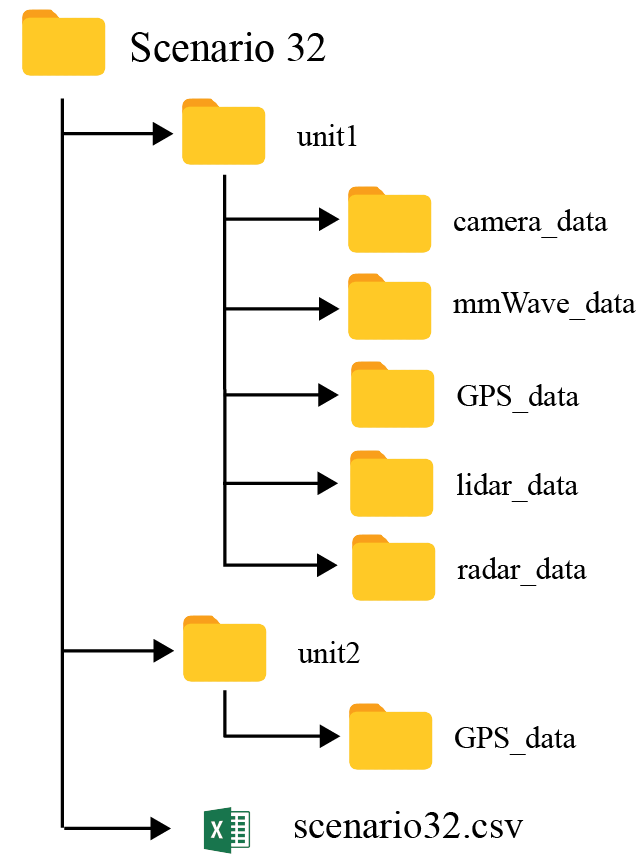
Scenario 32 folder consists of three sub-folders:
- unit1: Includes the data captured by unit 1
- unit2: Includes the data captured by unit 2
- resources: Includes the scenario-specific annotated dataset, data labels, and other additional information. For more details, refer to the resources section below.
The scenario 32 folder also includes the “scenario 32.csv” file with the paths to all the collected data. For each coherent time, we provide the corresponding visual, wireless, and GPS data.
Resources
What are the Additional Resources?
Resources consist of the following information:
- data labels: The labels comprises of the ground-truth beam indices computed from the mmWave received power vectors, the direction of travel (unit2), and the sequence index
- additional information: Includes the scenario-specific additional data. Details of the information is provided below
Data Labels
The labels comprises of the ground-truth beam indices computed from the mmWave received power vectors, the direction of travel (unit2), and the sequence index.
- Ground-Truth Beam: The phased array of unit 1 utilizes an over-sampled beamforming codebook of N = 64 vectors, which are designed to cover the field of view. It captures the received power by applying the beamforming codebook elements as a combiner. For each received power vector of dimension [64 x 1], the index with the maximum received power value is selected as the optimal beam index.
- Sequence Index: During the data collection process, the mobile transmitter (unit2) travelled multiple times in front of the base station (unit1). For each run, the testbed collects multiple data samples. All the data samples with the same sequence index belongs to the same run
Additional Information
We, further, provide additional information for each sample present in the scenario dataset. The contents of the additional data is listed below:
- index: It represents the sample number
- time_stamp [UTC]: This represents the time of data capture in “hr-mins-secs-ms” format
- unit2_num_sats: For each data sample, it is an integer value representing the number of connected satellites at that time instant
- unit2_spd_over_grnd_kmph: This represents the speed of mobility of Unit 2. Unit 2 is carried on a vehicle.
- unit2_mode_fix_type: This shows whether or not there was a 3D fix. A 3D (three dimensional) position fix includes horizontal coordinates plus altitude. It requires a minimum of four visible satellites.
- unit2_PDOP: PDOP (position dilution of precision) describes the error caused by the relative position of the GPS satellites
- unit2_HDOP: HDOP represents the horizontal dilution of precision
- unit2_VDOP: VDOP represents the vertical dilution of precision
- unit2_interpolated_position: a value of “0” denotes a captured data sample while a value of “1” denotes a data sample with an interpolated position from the captured data
Warning on NaN values: Some samples (<1%) in the column ‘unit1_pwr_60ghz’ contain NaNs (not-a-value). These NaNs result from random, real-world sensor errors. In the context of received power, NaNs can be considered as zeros. Assuming that pwr_vect is our received power vector, one can explicitly convert the NaNs into zeros by doing pwr_vect(isnan(pwr_vect)) = 0 in Matlab or pwr_vect[np.isnan(pwr_vect)] = 0 in Python.
An example table comprising of the data labels and the additional information is shown below.
| index | unit1_beam | unit1_max_pwr | time_stamp | seq_index | unit2_spd_over_grnd_kmph | unit2_num_sats | unit2_altitude | unit2_geo_sep | unit2_mode_fix_type | unit2_pdop | unit2_hdop | unit2_vdop |
|---|---|---|---|---|---|---|---|---|---|---|---|---|
| 1 | 3 | 0.174674109 | 01:22:30-405771 | 1 | 5.82 | 12 | 356.81 | -27.749 | 3 | 1.09 | 0.58 | 0.92 |
| 2 | 3 | 0.254460901 | 01:22:30-497819 | 1 | ||||||||
| 3 | 3 | 0.189701036 | 01:22:30-592039 | 1 | 5.862 | 12 | 356.814 | -27.749 | 3 | 1.09 | 0.58 | 0.92 |
| 4 | 3 | 0.212337449 | 01:22:30-683955 | 1 | 6.066 | 12 | 356.814 | -27.749 | 3 | 1.09 | 0.58 | 0.92 |
| 5 | 5 | 0.176145419 | 01:22:30-773664 | 1 | 6.351 | 12 | 356.807 | -27.749 | 3 | 1.09 | 0.58 | 0.92 |
| 6 | 2 | 0.224197328 | 01:22:30-864769 | 1 | 6.509 | 12 | 356.809 | -27.749 | 3 | 1.09 | 0.58 | 0.92 |
| 7 | 4 | 0.218475148 | 01:22:30-956300 | 1 | 6.599 | 12 | 356.806 | -27.749 | 3 | 1.09 | 0.58 | 0.92 |
| 8 | 2 | 0.213794827 | 01:22:31-135376 | 1 | 6.754 | 12 | 356.81 | -27.749 | 3 | 1.09 | 0.58 | 0.92 |
| 9 | 2 | 0.213794827 | 01:22:31-135376 | 1 | 6.883 | 12 | 356.806 | -27.749 | 3 | 1.09 | 0.58 | 0.92 |
| 10 | 4 | 0.217297301 | 01:22:31-227559 | 1 | 6.839 | 12 | 356.804 | -27.749 | 3 | 1.09 | 0.58 | 0.92 |