Data Collection
DeepSense Testbeds
- DeepSense Testbed 1
- DeepSense Testbed 2
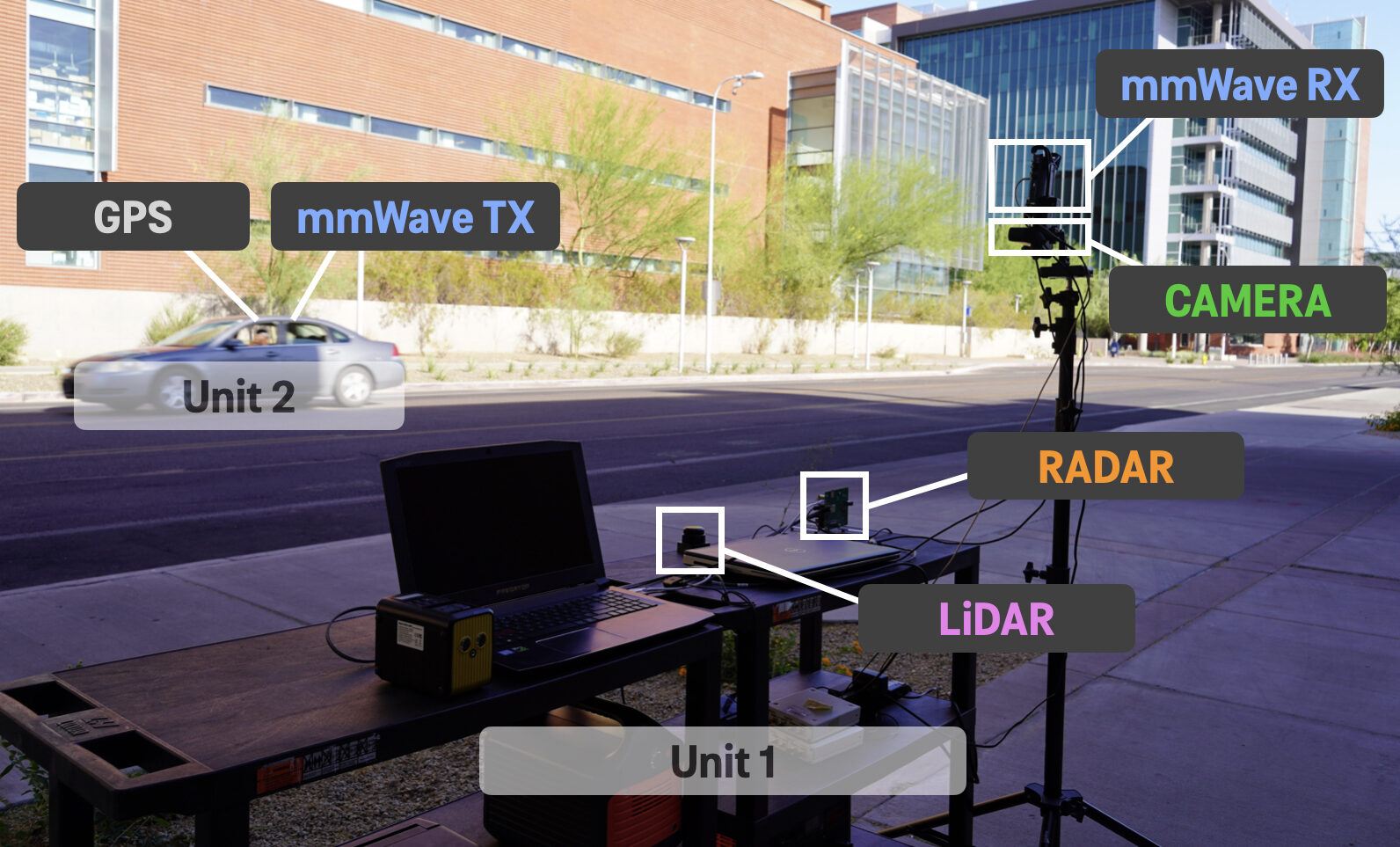
This testbed emulates a vehicle to infrastructure communication scenario with two units: Unit 1 (a stationary basestation unit with radar, LiDAR, camera, GPS sensors and a mmWave phased array receiver) and Unit 2 (a vehicle with GPS receiver and mmWave omni-directional transmitter)
Hardware Elements at Unit 1
RGB Camera
1100 FoV – 30 FPS – Wide Angle – f/1.8 Aperture
Output: RGB images of dimensions 960 x 540
mmWave receiver
60GHz phased array – 16-element ULA – 64-beam codebook
You can check and plot the exact (measured) beam patterns using this link:
Output: 64-element vector with the receiver power at every beam
Radar
FMCW radar with 3 Tx & 4 Rx antennas – fully-digital reception– 10 FPS – frequency range 76- to 81 GHz with 4 GHz bandwidth – Max. range ~ 100 m – Range resolution of 60 cm
Output: 3D complex I/Q radar measurements of (number of Rx antenna) x (samples per chirp) x (chirps per frame) : 4x256x128
LiDAR
Range: 40 m – 10 FPS – Resolution of 3 cm – FoV of 3600 – Accuracy ~ 5 cm – Wavelength ~ 905 nm
Output: 360-degree point cloud sampling data
Hardware Elements at Unit 2
GPS-RTK
10 measurements per second – Horizontal positional accuracy ~ 2.5m without RTK fix and ~ 10cm with RTK fix
output: Latitude and Longitude among other values
mmWave Transmitter
60GHz – Omni transmission (always oriented towards the receiver)
Data Collection Process

Scene Planning
The DeepSense 6G dataset consists of real-world multi-modal dataset collected from multiple locations in Arizona, USA (Tempe and Chandler). The primary aim of this dataset is to enable a wide range of applications in communications, sensing, and localization. In order to develop a diverse, challenging and realistic dataset to encourage the development of novel solutions for these varied applications, we adopt the following:
- Multiple locations: The 30+ scenarios in DeepSense 6G dataset were collected across more than 12 different indoor and outdoor locations with varying features such as busy streets in downtown with different vehicle speeds, streets with three-way intersection, parking lots to name a few. Each of the locations were carefully selected to capture challenging and realistic scenarios.
- Different communication scenarios: The dataset scenarios vary from vehicle-to-infrastructure communication, to drone communications, to communications with pedestrians, robots, and more, to cover the various aspects of beyond 5G communication use cases. The dataset scenarios/data also cover mmWave MIMO and sub-6GHz communication, and communication with Reconfigurable Intelligent Surfaces (RISs).
- Varying weather conditions: The weather conditions plays a critical role and can impact the performance of several sensing modalities such as vision, GPS and wireless data. For this, the data was collected during different weather conditions such as sunny, cloudy, windy and rainy with the temperatures ranging between 1o c to 48o c with the air humidity ranging between 5% to 97%.
- Different times of the day: To further increase the diversity of DeepSense 6G dataset, we collected data at different time of the day. From early morning to late-night, the scenarios of DeepSense 6G cover the entire spectrum.
DeepSense 6G not only consists of vehicular scenarios but also consists scenarios with humans and drones at the transmitter. Furthermore, to generate a realistic dataset, for the scenarios, we adopted different heights of the basestation and varying distance between the basestation and transmitter. For further details regarding the different scenarios, please refer here.
Sensor Alignment
As described in the DeepSense Testbed above, the different sensors such as the RGB camera, LiDAR and radar have varying FoV and range. To achieve a high quality multi-modal dataset with multiple sensors, it is essential to align these different sensors during the data collection process. We perform a number of calibrations steps prior to the collection of data to align the sensors taking into consideration the different range and FoV.
Sensor Data Synchronization
The different sensing elements such as the mmWave receiver, RGB camera, GPS RTK kit, LiDAR and radar have varying data capture rate. Note that the mmWave receiver runs at 8-9 Hz, camera captures data at 30 Hz while the GPS RTK kit runs at 10 Hz. Therefore, in order to achieve meaningful data, cross-modality data alignment is necessary. We undertake a series of actions in order to achieve the necessary alignment. For example, the exposure of the camera is triggered right after the beam sweeping is completed. Since the camera’s exposure time is nearly instantaneous, this method generally yields good data alignment between the camera and the mmWave receiver. Further, the timestamp of the image capture and the GPS data is stored. The timestamp helps in aligning the image, mmWave and GPS data during the post-processing. Similar steps are performed for the other modalities to ensure coherent data for each time step.
Data Collection Map
The scenarios in DeepSense 6G dataset was collected across different locations in Arizona, USA. In this section, we provide the data collection map highlighting the different location utilized for the data collection.
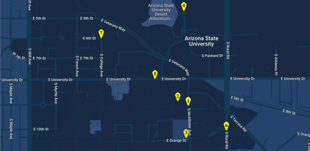
Tempe, Arizona, USA
DeepSense 6G: Tempe
1. McAllister Ave.
2. ECEE Dept., ASU
3. BioDesign ASU
4. Lot-59
5. University Drive
6. Rural Rd.
7. College Ave.
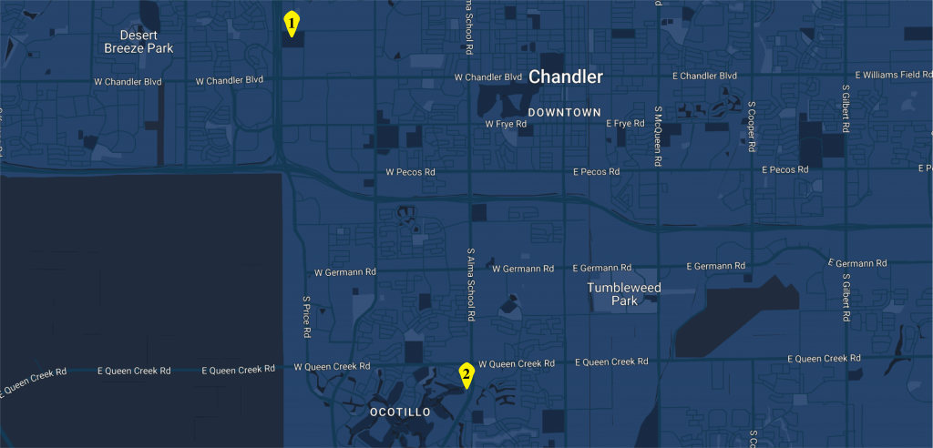
Chandler, Arizona, USA
DeepSense 6G: Chandler
1. Thude Park
2. Alma School Road